Real-time identification of tiny features of steel lap lap welds Text / Chen Haiyong Abstract: A method for image feature recognition based on structured light vision is proposed for steel lap welds. Using the principle of spatiotemporal correlation and image morphology to eliminate some random noise and improve image quality. Using the peak detection method, the region of interest is determined and the calculation efficiency is improved. Furthermore, the feature points of the structured light strip are extracted by column search and distance difference method, and the experimental results achieve the desired performance. Key words: lap joint; machine vision; feature extraction; laser structured light 0 Preface Thin steel plate lap welding resistance welding is widely used in the steel drum industry. The development of lap welding system has great social and economic benefits for reducing labor intensity, improving production conditions, improving production efficiency and optimizing weld quality. In recent years, in order to realize the automation and intelligence of the welding process, researchers at home and abroad have conducted a lot of research on the image recognition of weld seams. Prof. FAbt from the University of Stuttgart, Germany, and Professor Zhang Yuming from the University of Kentucky in the United States studied the relationship between the weld pool and the quality of the weld; the University of Glasgow, Camarasa, proposed a binocular vision system that can identify and determine targets in a messy scene; Western Australia University Mitchell, Ye et al. achieved robust identification and weld location of welds under illumination, reflection and other conditions. Professor Chen Shanben of Shanghai Jiaotong University mainly studied welding from the dynamic shape of the molten pool; Professor Zhao Mingyang of Shenyang Institute of Automation and others studied robotic laser stitching welding; Professor Du Dong of Tsinghua University and others studied color information to identify multi-layer multi-pass welding and pipeline welding. Researcher Xu De of the Institute of Automation, Chinese Academy of Sciences and others conducted in-depth research on the image processing of V-weld weld seams; Professor Jiao Xiangdong of Beijing Institute of Petrochemical Technology mainly studied underwater welding and spherical can welding of robots. At present, these studies mainly focus on the image identification of weld seams with obvious features, but the identification of lapped micro welds still needs further study. To this end, this paper mainly studies the identification and extraction algorithm of lap weld feature points. 1 Vision system composition The principle point extraction principle of lap welds based on structured light is shown in Fig. 1. The entire vision system is mainly composed of CCD cameras, line structure light emitters, filters and other components. The CCD camera is perpendicular to the welded workpiece, and the linear structured light emitter emits an elongated red line on the workpiece. The filter is mounted in front of the lens to filter out some of the interference light information. It can be seen from Fig. 1 that the line structure light is struck on the welded workpiece, and the height difference caused by the lap joint will cause the two sections of the structured light respectively struck on the welding plate to be in a parallel state, and it is necessary to find two welding feature points. The jump point of the parallel line. 2 image processing Image processing algorithm design is a crucial part of the visual welding system. Its essence is to process the image information collected by the vision sensor, retain useful information, and weaken or remove noise interference. For the small feature recognition of the lap weld, this paper separately performs a series of processing such as image filtering, and the processing flow is shown in Figure 2. 2.1 Image enhancement In the real-time welding process on site, due to the interference of arc, strong heat, splash, etc., there are many noises in the image. These noises are mainly linear and block-shaped, and the real-time images collected are shown in Fig. 3(a). Therefore, image enhancement processing is required before image feature point extraction is performed, even if the required information is more prominent, and conversely, the unnecessary information is weakened, and the processed image is more easily recognized by the machine, which is advantageous for feature point extraction. Figure 3 captured real-time image When acquiring image information in real time, based on the principle of space-time correlation, considering the stripe has a certain width, the real-time welding motion speed, etc., in the case of the processing speed in the order of ms, the position of the image stripe between adjacent frames in the image The change is slow, and the spatter noise in the image is very random, so the image is operated and operated: Where: Ft(i,j) is the image acquired at time t; Ft(i,j) is the image acquired at time t-1; F't(i,j) is the image after the image is processed and operated. In this way, after the image and the operation, the interference of the random noise caused by the arc splash or the like can be filtered, and the stripe has a certain width, which does not greatly affect the line position recognition. In general, the image has a locally continuous property, that is, the values ​​of adjacent pixels are similar, and the presence of noise causes a grayscale transition at the noise, and the average local filtering is applied to the local noise of the image, and the gray value of the noise point is corrected. , to achieve image smoothing. Let f(i,j) be the image containing noise collected by the camera. After the average template filtering process of the neighborhood is g(i,j), then g(i,j)=Σf(i,j) /N(i,j)∈M, M is the coordinate of the neighboring pixel in the neighborhood in the filtered template, and N is the number of neighboring pixels contained in the neighborhood. The larger the size of the template, the more blurred the image after processing. In this embodiment, the filter template uses a template with a size of 3*3, which is It can be seen from the comparison of the two images that the local block-like noise points in the image are effectively corrected, the gray value of the neighborhood is changed gently, and the edge of the image is smoothed, which weakens the interference caused by the arc during the welding process. 2.2.1 Image binarization In order to further highlight the contour of the object of interest, it is necessary to binarize the grayscale image. In order to get the ideal binary image, you must choose the appropriate threshold. Since the middle of the stripe is brighter and the sides are darker, it is not appropriate to use the same fixed threshold for the entire image. The threshold selection method, the maximum inter-class difference method (referred to as the OTSU method) is proposed below. The OTSU algorithm is simple to calculate and is not affected by image brightness and contrast, so it has been widely used in digital image processing. It divides the image into two parts, the background and the foreground, according to the grayscale characteristics of the image. The larger the variance between the background and the foreground, the greater the difference between the two parts that make up the image. When part of the foreground is misclassified into the background or part of the background is divided into the foreground, the difference between the two parts will be smaller. Therefore, the segmentation that maximizes the variance between classes means that the probability of misclassification is minimal. Let the gray level of the gray image be L, then the gray range is [0, L-1], and the optimal threshold for calculating the image using the OTSU algorithm is: Variable description: When the threshold of the segmentation is t, w0 is the background ratio, u0 is the background mean, w1 is the foreground ratio, u1 is the foreground mean, and u is the mean of the entire image. 2.2.2 Image Morphology After the image is binarized, there is still some interference. In order to further eliminate the interference, it needs to be processed again. The morphological opening operation is performed by first performing an etching operation on the image and then performing an expansion operation. Corrosion operation removes discrete points in the edge of the image, and the expansion operation restores the remaining information to the original appearance, thus filtering out noise without affecting the image contour. The open operation can be expressed as: The effect after the image is opened is shown in Fig. 5. 2.3 Extracting feature points 2.3.1 Determining the area of ​​interest The image captured by the camera is spread over the entire image area, and the area required to process the image is only the area containing the structured light stripe, which effectively extracts the region of interest, which not only improves the stability, but also avoids noise in other areas of the image. The interference caused in the process, and the smaller image processing range, improves the processing speed of the algorithm. By calculating the brightness of the structured light stripe line by line, find the line where the two peaks are located, and the longitudinal coordinates of the 2 stripe are respectively recorded as y1, y2. At this time, the image region of interest (ROI) can be determined, and the longitudinal direction range [min(y1, y2)-20, max(y1, y1)+20]. Since the discontinuous breakpoint may occur at the stripe sign of the lap plate, the nearest neighbor interpolation method is used to obtain a continuous stripe line, namely: f(x,y)=g(round(x),round(y)), (4) Where: f(x, y) is the filtered image; round is the rounding operation. The nearest neighbor interpolation method is simple to calculate, the program runs less time, and the output result does not affect the processing of key information. The determination and interpolation results of the region of interest are shown in Figure 6. 2.3.2 Structural light stripe skeleton extraction The most commonly used methods for determining the center skeleton of a structured light stripe are threshold method, extreme value method, center of gravity method, and the like. The threshold method is based on the left and right pixels whose threshold value is greater than or equal to a certain value as the starting point and the ending point, and the average position of the two is the center of the structured light stripe; the extreme value method is to use the maximum intensity point as the structural light center skeleton; For the improved extreme value method, firstly, the extreme value method is used to find the maximum position of the light intensity, and then the k points around the position are taken, and the center of gravity of the k+1 point is obtained, which is considered to be the central skeleton of the structured light stripe. The inaccurate extraction of individual pixel points by these three methods will have a large impact on the results. In the ROI area, the center line array of the weld stripe is extracted. In this paper, the center line array of the stripe is obtained by the column-by-column search method. The stripe has a certain width on the soldering plate and needs to be refined to extract the unique stripe coordinates in the column direction. The basic idea of ​​refinement is to keep the original shape of the image, and remove the edge points, that is, to maintain the original skeleton of the image. The purpose of refinement is to extract a unique array of stripe centerlines. Based on the principle of stripe refinement, the author proposes a column-by-column search method to obtain an array of centerlines of stripes. Sum1=2*(f(i,j-1)+f(i,j+1)), (5) Sum2=f(i,j-8)+f(i,j-6)+f(i,j+8)+f(i,j+6), (6) Delta=sum1-sum2, (7) The maximum delta value is obtained, and the corresponding j value is the longitudinal coordinate of the extracted corresponding contour. At this time, f(i, j) is the extraction result. 2.3.3 Determination of stripe validity The extracted feature points may cause large deviations of the feature points due to noise, etc., and it is necessary to judge the effectiveness of the extracted stripe skeleton to ensure that the extracted stripe feature points are effective. Find the average value of each extracted feature, and the error is greater than 30 pixels, which is a large jump point, which needs to be removed. Where: f(i,j) is the extracted feature point; aver is a mean value calculation performed after each feature point is extracted. The feature point value after culling is assigned the value aver. 2.3.4 Distance difference method to extract feature points After the interpolation method is used to obtain continuous stripes, and the stripe skeleton is obtained by the column-by-column search method, the next step is to determine the welding feature points, which are displayed as two striped transition points on the image. The common method is to find the maximum point of the gradient by the gradient value, but this method is computationally intensive and affects the real-time effect of the system. This paper uses a distance difference method to extract the weld feature points. The image contour f value of the adjacent 10 points is sequentially taken, and the distance difference meter is performed. d=[max(y1,y2)-min(y1,y2)]*5*Δ, (9) Where: d is the sum of two distances; y1, y2 are the longitudinal coordinate values ​​of the two stripe that have been extracted; Δ is the distance weight, which is used to correct the deviation of the distance superposition value, which ranges from 0.7 to 0.9; D is The sum of the continuous point distance differences on the image. When the condition D>d is satisfied, the welding feature point is found, and the i value is corrected for correcting the coordinate deviation of the superposition. In this case, the i+6 value satisfying the condition is the lateral coordinate value of the feature point, (y1+y2) /2 is the feature point longitudinal coordinate value. In the field welding process, high-frequency noise and other disturbances exist in large quantities. In order to further improve the stability and reliability of feature point extraction, the second-order difference method is used to correct and supplement. Y(i,j)=f(i+2,j)-2*f(i+1,j)-f(i,j). (11) The second-order difference value Y(i,j) at the extracted maximum point is the feature point. The feature values ​​extracted by the distance search method are compared with the feature values ​​extracted by the second-order difference, and the difference between the two values ​​is less than 10 pixels, which is legal, otherwise the next round of calculation is performed. 3 test results Through the above steps, the square in Fig. 7 is the welding feature point extraction result. As can be seen from the figure, the laser stripe is clearly divided into two straight lines, and the welding feature points are the linear jump points caused by the change in the overlap height of the steel sheets. In order to verify the real-time and reliability of the algorithm, the feature points in the welding process are extracted in real time, and the straight lines with different slopes are extracted separately. By controlling the movement of the actuator, the sensing mechanism is moved at a uniform speed of 1 m/min to extract the feature point coordinates, and two different slope welds are selected as shown in Figs. 8a and b. The horizontal and vertical coordinates of the extracted feature points are fitted to obtain the results of tracking and fitting data. The extracted X and Y data are shown in Fig. 8c, d, e, and f. It can be seen from the figure that the real-time extraction accuracy of coordinates is high and the extraction result is stable and reliable. The algorithm has a faster processing speed and a speed of 14 frames/s, which enables real-time welding requirements. 4 Conclusion For the lap welding intelligent system, the image processing speed is the key. For the lap welding of thin steel plates, this paper completes the image enhancement noise reduction process through a series of algorithms such as spatiotemporal correlation principle and morphological opening operation, and then passes the peak detection method. The region of interest is determined, the computational efficiency is improved, and the stripe skeleton is accurately extracted by the column-by-column search method. Finally, the feature points are obtained by column search and distance difference method, and the processing speed is faster. This paper fully considers the various interferences encountered in the real-time welding process, and combines a series of reliable processing processes with the characteristics of structured light graphic images. The processing speed is fast and can meet the requirements of real-time tracking of welds. When it comes to decorating a bathroom, many people often neglect the doors. That`s such a real mistake since the doors can make a huge difference. To get an outstanding result, you must include aesthetic and practical perspectives in the design of bathroom doors. Moreover, the materials range drastically from wood to steel. So, pick the best one that articulates your taste. Bathroom Doors,Modern Bathroom Doors,Waterproof Bathroom Door,Bathroom Door With Glass HOPE IKEA , https://www.skyfurnishing.com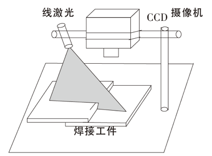
Figure 1 Schematic diagram of the lap weld vision system 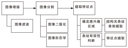
Figure 2 image processing flow chart 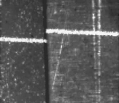
(a) original image 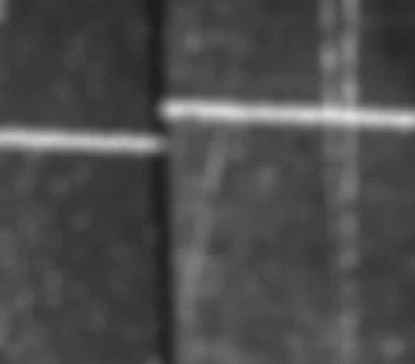
(b) Filtered image ![]() (1)
(1) ![]() The middle black dot represents the element to be processed. The filtering result is shown in Figure 3(b).
The middle black dot represents the element to be processed. The filtering result is shown in Figure 3(b).
2.2 Image segmentation
Image segmentation is a technique and process that divides a digital image into mutually disjoint (non-overlapping) regions. Image segmentation is a key issue in image analysis. Image segmentation can highlight areas or scenes of interest in an image. ![]() (2)
(2)
The value of t that maximizes the value of the above expression is the optimal threshold for segmenting the image. Figure 4 shows the result of binarization of the image by the OTSU algorithm. 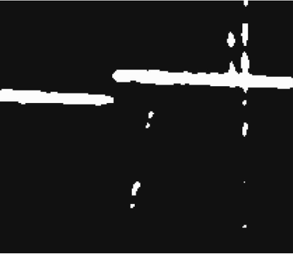
Figure 4 OTSU algorithm binarized image ![]() (3)
(3) 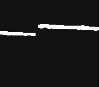
Figure 5 Morphological open operation results 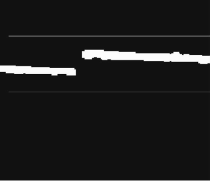
Figure 6 Determine the ROI ![]() (8)
(8) ![]() (10)
(10) 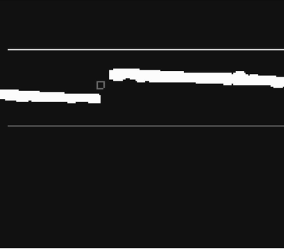
Figure 7 Feature point extraction results 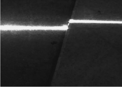
(a) Weld 1 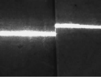
(b) Weld 2 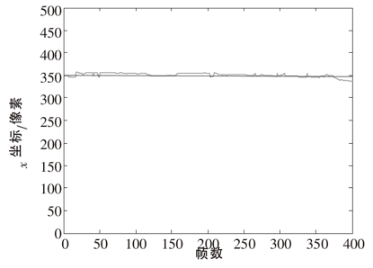
(c) x coordinate change of weld 1 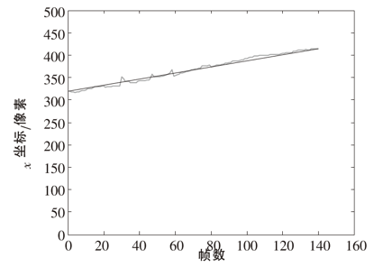
(d) x coordinate change of weld 2 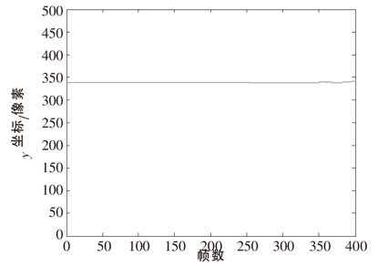
(e) y coordinate change of weld 1 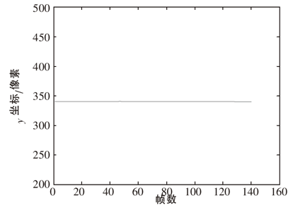
(f) y coordinate change of weld 2
Figure 8 extracted x, y data map